EVOLVE Fabrication - Bend Calibration
https://foresite.evolvemep.com/
Crippa Machine Profiles

The Crippa CNC tube bending machine supports creating bends for several different sizes and types of conduit and pipe. The EVOLVE Fabrication Website maintains profiles for the Crippa CNC. These profiles are used to generate the bend angles and leg lengths to allow the conduit to be bent to match the designed part.
Basic Usage
- Open Evolve Fabrication (cloud).
- Select Fabrication
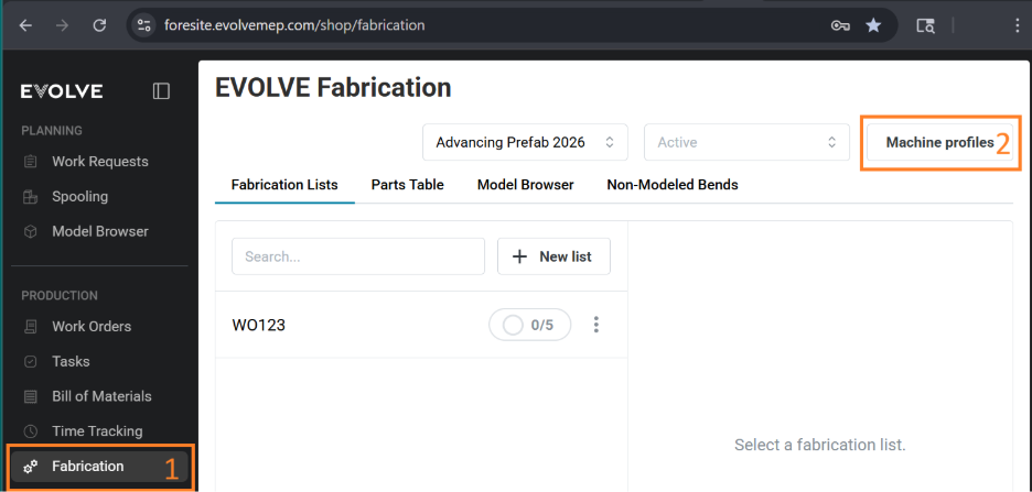
- Select Machine Profile (upper right of window).
- Select + or Create New Profile.
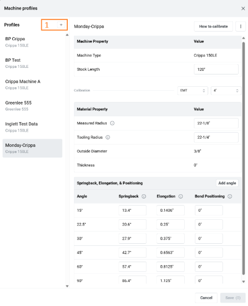
- Enter a name for the profile (e.g.
CRIPPA150LE). - Enter the specific machine/material information:
- Material Length — 10 or 20 ft conduit.
- Material Type & Size — EMT, IMT, RMC — ¾" to 4".
- Measured Radius — A generic measurement will be input into the box; this is determined by the size of the tube selected. Can be adjusted later in the procedure.
- Tooling Radius — Radius for conduit size as defined in the
Tooling.SPFfile for your machine. (Do not adjust or change this value.)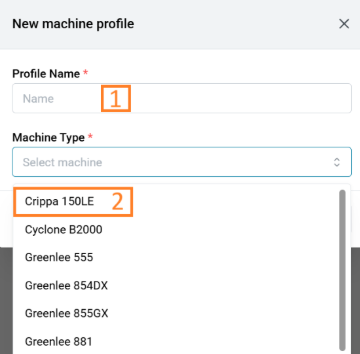
- Spring Back
- Measured Radius
- Elongation
- Bend Positioning
Common Actions
- Create Profile: To create a profile, click the plus icon in the upper left. You can create several profiles for the different machines you have.
- Profile Name: Enter a name for the profile. e.g. Material Vendor, Machine name, Hot day, Cold day.
- Material Type: EMT, IMC, RMC.
- Material Size: Select the conduit size. ¾" - 4".
Determining Spring Back
- With your example Revit project, send the test bends to Fabrication (link to example Revit project) — offset and back-to-back bends and a saddle for verification.
- Select the diameter you would like to create a profile for.
- Select the number of bends you would like to use to build your profile. (We provide 15, 22.5, 30, 45, 60, 90, but have seen success with as little as 15, 30, 60, 90.)
- Load the bends to Fabrication.
- Bend all the angle bends with the profile at the default values.
- Measure the bend angle for each bend, ensuring you are measuring from the nose to the first bend — not the tail to the first bend, even if the tail is longer and it seems easier. You need to measure the angle from nose to bend.
- Write the measured values on a piece of paper. (Do not input the values into the files yet!)
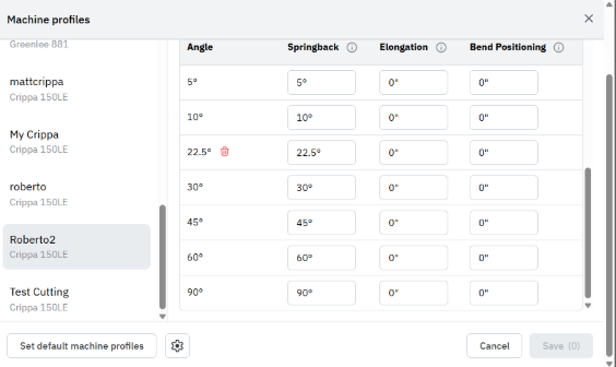
- Once all the bends are bent and angles measured, enter these angles into the spring back table and save the profile.
- Repeat steps 1–7 a couple more times, adjusting the angle until the desired angle is achieved.
- If the bend angle is still below target, decrease the spring back value.
- If the bend angle is above target, increase the spring back value.
- Refresh the Fabrication app on the Crippa.
Determine Measured Radius
From here forward, measure the length of the conduit before you bend it (before-bend measured conduit length).
- Bend the back-to-back 90° a second time using the new spring back values.
- Verify both angles are correct, ensuring you are measuring from the nose to the first bend.
- Once the bend angles are acceptable: (the closer the bend angle is to exact, the more precise the measured radius will be)
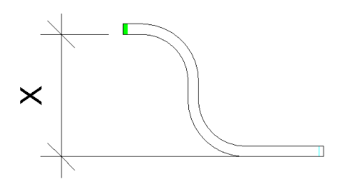
- Place the top of the nose end against a flat surface and measure from the flat surface to the bottom of the upper horizontal leg of the conduit.
- Reference the MPF / YBC file and look up
R102. - Calculate the measured bend radius: (measurement (X) − R102) / 2
- Enter the measured bend radius into the profile.
- Refresh the Fabrication app on the Crippa.
Determine Elongation
From here forward, measure the length of the conduit before you bend it (before-bend measured conduit length).
- Bend each bend a second time. (You can use the back-to-back 90° you already bent with correct angles, and you already know the before-bend measured length.)
- Verify that both angles of each bend are correct, ensuring you are measuring from the nose to the first bend.
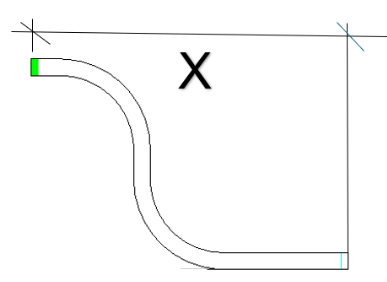
- Once all the bend angles are acceptable, measure the length of the conduit. Square the conduit on a flat surface and measure from the surface to the end of the conduit — do not measure across the bends. This is your after-bend measured conduit length.
- If you are using a full-length conduit (e.g. 120"), mark the conduit to the Revit project length — this is your before-bend conduit length.
- Place the marked end facing out of the machine when loaded into the Crippa.
- Check the model in Revit and determine what the actual length of the conduit should be. This is the before-bend conduit length value.
- Subtract the measured (X) after-bend conduit length value from the project's actual length.
- Divide the result by 2.
- Enter the value in the Machine Profile table and Save.
- To verify the elongation correction:
- On a new piece of conduit, place a mark at the full length of the conduit minus the difference obtained in step 5 (e.g. 120" − .6250").
- Bend the marked conduit, ensuring the mark is facing out of the machine.
- Re-measure to the mark — this should be equal to the value in the Revit model.
- Repeat for each angle.
- Once all the elongation values are collected, enter them into the machine profile.
Determine Bend Position Error
The bend positioning error is used to alter the nose length before the first bend to account for errors created when loading the conduit.
- To determine the bend position error, one must be able to identify
- the marks on the conduit from the pressure die and the bend clamp.
- All tooling has a 1/8" spacing between these two pieces of tooling.
- The Bend position error is going to be the difference between the mark made by the pressure die and the end of the conduit.
- Generally, this is a very small number.
Verify the profile produces parts correctly
- Manufacture the 4-point saddle and measure to ensure everything is correct
